Conversion of Philips FM1000 STM23 (ex german Bündelfunk) for
70 cm amateur radio use
The FM1000 series of PMRs can be easily converted for 2 m or 70 cm
amateur radio use. Excellent descriptions of the conversion can be
found at www.fm1000.com or www.pa4den.nl/fm1200.html,
including the contents of the necessary EPROMs. All these conversion
instructions assume that you have the numeric keypad control head or
the standard control head, but not the standard control head for
trunking systems.
However, there are lots of ex Bündelfunk STM23 type radios with
exactly that trunking control head available for a moderate prices. It
seemed as if it was impossible to convert these STM23s for amateur
radio use. As an engineer, I was unwilling to accept this, but realized
that I had to start my own activities to make them usable for amateur
radio.
The starting point was a working STM23 with numeric control head using
the excellent firmware of PA4DEN. This combination is the ultimate
solution for 70 cm amateur radio; you get a really nice transceiver.
Why should I not use parts of Dennis' work? I tried to figure out the
communications between main radio unit and control head. Storage
oscilloscope, logic analyzer and async sniffer are mandatory for that.
However, it was not as easy as I thought it could have been. That was
the point where I contacted PA4DEN and just asked if he could tell me
the protocol used. He kindly sent the protocol description, that saved
a lot of work. Thanks, Dennis!
After several weekends of programming and testing, I finally had a
firmware for the standard trunking control head that was basically
working. Of course, you have to keep in mind that the feature list is
somewhat modest due to the limited display capabilities of the control
head. You have only two group of numeric displays, one with 2.5 digits
and one with 3 digits, plus a few symbols. Another limitation is that
Dennis' firmware for the main radio unit was not intended for use with
a
control head with only limited capabilities.
These are the features of my firmware:
- Frequency up/down in 12.5 kHz steps
- Memories
- VFO and memories scan
- Repeater shift 7.6 MHz (others possible)
- Reverse shift to listen at the repeater input
- Squelch open function
Important: A lot of these parameters (step size, repeater shift, power,
squelch etc.) depend on configuration stored in the EEPROM. Presently
these are standard settings I think to be OK. They can be changed using
temporarily a numeric control head. This is not too nice, but there may
be a PC program to generate the configuration EEPROM content in
the future.
Important: This firmware is in BETA state (2004 Sept). There are known
bugs an probably will be more.
Conversion of the trunking control head
This part is recommended for experienced experimenters only!
Verification of control head type
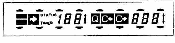
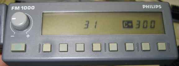
First, verify if you really have a trunking control head. This usually
cannot be seen without activating it. Switch on the radio using the
original trunking software. In the first second, all segments of the
display come up. The trunking control head LCD should look like this:
If it does not look like this, it is probably not a trunking control
head. You are lucky then, you don't have to use my firmware! In this
case, please refer to www.fm1000.com;
there is plenty of information how to convert a non-trunking FM1000.
Conversion of control head
The conversion of the trunking control head is definitely not as easy
as the conversion of the numeric control head. You have to remove the
original PLCC EPROM without damaging the PCB tracks and then you have
to replace it with a new one. With the trunking control heads I have
seen, there is no PLCC socket and it is not possible to add a PLCC
socket since then it is not possible to fit the enclosure anymore.
Personally, I use a quite crude trick to remove PLCC PROMs which are
directly soldered to the PCB and I never ruined a PCB using this
method. I take a very sharp knife or blade and just cut the PLCC
pins directly at the IC body. Be careful to cut orthogonal in respect
to
the PCB and do not bend the cut pins. When you have cut all 32
pins, the IC body (with no pins anymore) can be taken off easily. The
32 pins remain on the PCB pads and can be removed by carefully heating
them up with a fine tip soldering iron and pulling them away from the
PCB.
Now the programmed replacement 27C256 can be soldered in. Inspect all
32
pins for firm contact to the PCB pads; missing soldering joints
are easily overlooked.
Conversion of main radio unit
Please refer to PA4DEN's instructions to convert the main radio unit.
Test
After switching on the radio, it should be possible to step the
frequency
up and down. You may want to checkout if receiving and transmitting
work.
Remember to use a dummy load; never transmit without antenna or dummy
load.
Operation
Key number (from left)
|
Function
|
1
|
Squelch open (RX), 1750 Hz (TX)
|
2
|
Frequency/Memory down
|
3
|
Frequency/Memory up
|
4
|
VFO - Memory (indicator when
Memory mode)
|
5
|
Memory frequency - Memory number
(indicator when number)
|
6
|
Scan '*'
|
7
|
Repeater shift '#'
|
8
|
Function button
|
1750 Hz repeater access tone can be generated by pushing either SQ/1750
Hz button or the auxiliary button at the microphone while transmitting.
To use the 1750 Hz option, you have to do the ZVEI/CTCSS modification
of the main radio unit as described in PA4DEN's manual.
Please refer to the original PA4DEN manual for operation - please keep
in mind that all functions rely on his firmware for the main radio unit.
LCD photos
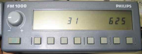
Normal
operation, squelch closed, RX 439.225 MHz
Reverse
shift, listening on repeater input 439.225 MHz - 7.6 MHz
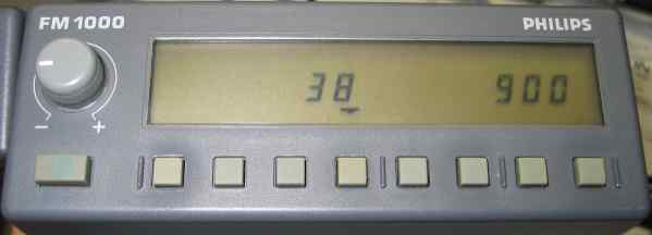
Memory
mode, 438.900 MHz
Receiving,
squelch open
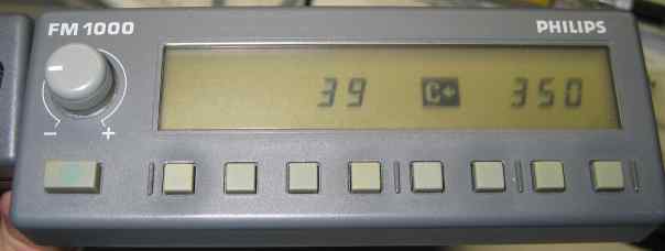
Transmitting
on 439.350 MHz - 7.6 MHz
Differences/Special cases
There are some special cases due to the limited capabilities of the
trunking control head:
- Frequency is displayed with the leading "4" missing,
e.g. 438.900
MHz is displayed as "38 900".
When using 12.5 kHz steps, e.g. 439.3875 MHz is display as "39 387".
- Entering scan edge frequencies: Select lower edge
frequency using
up/down keys in VFO mode. Press FUNC, SCAN, FUNC. Select upper edge
frequency, press FUNC, SCAN, SCAN. Now the edge frequencies are
programmed. You may start scanning with SCAN. When in Memory Mode, the
used memories are scanned.
- Repeater shift: Unfortunately, there is no visual
feedback. Press
FUNC, REPEATER until the second beep is a low one. This is Simplex.
FUNC, REPEATER switches to -7.6 MHz (high second beep), another FUNC,
REPEATER switches to +7.6 MHz (high second beep), yet another FUNC,
REPEATER (low second beep) switches back to Simplex. Pressing REPEATER
without FUNC while in VFO or memory mode switches to the repeater input.
- Entering memory frequencies: Switch to Memory number
mode (Key
5). Select the desired frequency with the up/down keys and possibly
repeater shift. Press FUNC, VFO/MEMORY and select a free memory channel
with the up/down keys. Only empty memories are displayed, but you may
select used ones by counting the beeps [this may be considered a bug...
will try to fix that]. Press FUNC twice to store.
Acknowledgements
Thanks to Dennis Koller, PA4DEN, who wrote the main radio firmware and
kindly
provided for details on the communication between main
radio unit and control head. Thanks to James Miller, G3RUH, who
proofread this text.
EPROM images
Until the firmware is out of the BETA stage, I would like to send out
the images by personal email. Please send an email with your call sign
to 
LCD transparencies
DC3TC made nice display transparencies, thank you Tobi. You can use either
this MS-WORD file
or
this PDF file to print them.
Known bugs
- Display goes crazy when switching repeater offset on/off.
Operation can be completed by listening beeps, normal operation is
restored by switching radio off/on (with front panel switch! When
switching the power supply, changes in configuration are not stored)
Bug reports
Bug reports (as detailed as possible please) are highly appreciated,
send email to (due to spam protection, you have to enter this email
adress manually into your mail client).
Important statement
This is a hobby project. It started because I was unwilling to
accept that all these STM23's, with the trunking control head, should
be
useless. It is my intention to help fellow radio amateurs convert these
fine radios for their personal use. The trunking control head firmware
is provided free of charge for non-commercial amateur radio use, but
any possible liability is denied. Use it, get happy, if you blow up
your radio, it's not my fault.
Last modified: 02.01.2005